Rack and Row Guidelines
Rack Standards
Layout
- Data center rack enclosures must be 48U to maximize horizontal space.
- The preferred width is 24 inches with vendor neutral mounting rails that are fully adjustable and compatible with all EIA-310 Electrical Industry Alliance Standards compliant with 19” wide equipment. Any exceptions will have to be cleared by data center management.
- Rack enclosures must have access points for power at the bottom of the rack, and access points for data pathways at the top of the rack.
- Rack depth is usually not a concern, but deep racks are preferred, not to exceed 4 feet.
- Cut floor tiles must use approved floor grommets to maintain under-floor air pressure and to prevent excessive airflow issues.
- The top 6U of each rack is reserved for network infrastructure, the rest of the rack for compute and storage devices. The heaviest units, like storage, should be located at the bottom of the rack.
- Data cabling should be above the rack preferably in independent, suspended cable tray lanes and maintained in an orderly fashion.
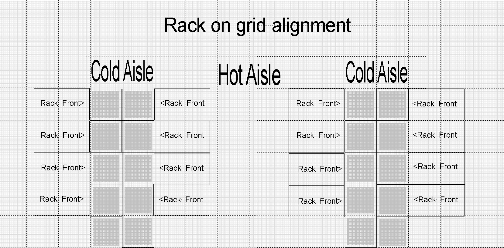
- The front of the rack should be lined up with edge of the floor tiles. Racks will
be identified by the data center grid with the front of rack determining the location
on the grid.
Note: See Example 1 below. - All racks must be lockable, and it is up to the owner whether they remain locked. If locked, a key must be provided to OPS for emergency purposes and stored in the key cabinet in ADSB-123.
Power
- Vertical rack PDUs are preferred and must be metered and addressable remotely for emergency shutdown needs.
- When powering down in an emergency, the storage units should be powered down last.
- Power information cards will be created for each rack to identify the UPS, PDU, panel,
circuits, voltage and connector type that each rack pdu is powered from. Labels will
be placed on the in-rack pdus for identification unless there are only 2-rack PDUs.
In this case a simple “right” and “left” PDU identifier is sufficient. These will
be attached to the rear of the rack for easy identification.
Note: See Example 2 below.
Row Standards
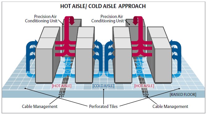
- All rows will be arranged with the hot aisle/cold aisle as determined by the data
center manager.
- All rack and row placements will be determined by data center master floor plan, space availability, and adherence with existing deployed rack and row configurations.
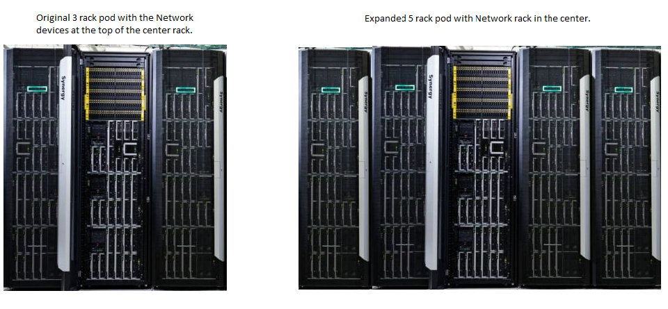
- A row will be provisioned as pods of up to 5 racks per pod.
- A rack pod will be provisioned first with three racks, with the base networking in rack 3, due to cabling restraints. The rack pod will be expanded by adding two racks to the right of the original three.
- The row will be expanded by setting three new racks to the right of pod A. Then the row will be filled out by adding the final 2 racks.
- A full row should not exceed a total of 10 racks (2 pods). HPC may be the exception; they are using 11 racks with the Net rack in the center.
Example 1
Example 2
Rack ID: VDI
Location: X-12-Front of rack
Owner: UITS Virtualization Team
| UPS | PDU | Panel | Circuits | Voltage | Connector | In-Rack PDU # |
|---|---|---|---|---|---|---|
| 4 | 7 | 3 | 8, 10, 12 | 220 | CS8364C | #1 |
| 4 | 7 | 4 | 34, 36, 38 | 220 | CS8364C | #2 |
| 2 | 10 | 1 | 12, 14, 16 | 220 | CS8364C | #3 |
| 2 | 10 | 3 | 10, 12, 14 | 220 | CS8364C | #4 |